Summer Research Presentation
This presentation was given at the end of the Wake Forest University
Biomedical Engineering and Informatics Summer Research Internship Program.
 My name is Calvin Smith and today I will be presenting a new software developed for in situ bioprinting.
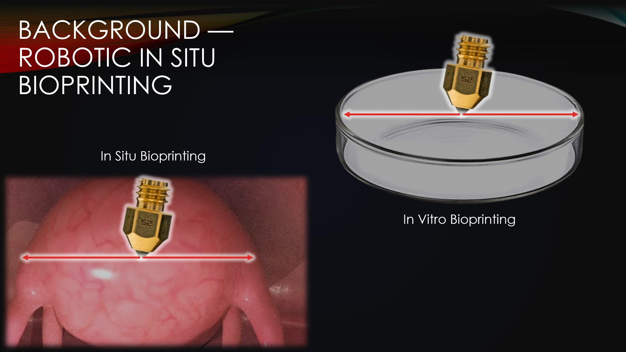 In situ bioprinting is when you directly deposit tissue into the body, as opposed to in vitro bioprinting, where tissue is deposited in a lab.
Right now, surgeons are able to do in vitro bioprinting, but this method takes a long time.
You have to first imaging a wound, then print a tissue, and then transplant it into the body.
This process can sometimes take weeks and in this time, the wound may drastically change form, making the printed tissue no longer viable.
With in situ bioprinting, the entire procedure can be done in one surgery.
In situ bioprinting is when you directly deposit tissue into the body, as opposed to in vitro bioprinting, where tissue is deposited in a lab.
Right now, surgeons are able to do in vitro bioprinting, but this method takes a long time.
You have to first imaging a wound, then print a tissue, and then transplant it into the body.
This process can sometimes take weeks and in this time, the wound may drastically change form, making the printed tissue no longer viable.
With in situ bioprinting, the entire procedure can be done in one surgery.
 Any automated robot, like a bioprinter, needs to be sent movement commands, AKA toolpaths.
For in situ bioprinting, these toolpaths need to be quickly generated during the surgery.
There are currently no effective ways to do this.
The goal of this project was to create a simple, accurate, and fast toolpath generation software.
Any automated robot, like a bioprinter, needs to be sent movement commands, AKA toolpaths.
For in situ bioprinting, these toolpaths need to be quickly generated during the surgery.
There are currently no effective ways to do this.
The goal of this project was to create a simple, accurate, and fast toolpath generation software.
 Now, I will discuss the methods used to develop the software.
 To begin a bioprinting surgery, the robot must first be quickly jogged to the correct starting location.
Jogging is the process of manually moving an automatic machine.
Here is a traditional CNC mill’s jogging interface, and here is the software’s jogging interface being used to suture a practice pad.
To begin a bioprinting surgery, the robot must first be quickly jogged to the correct starting location.
Jogging is the process of manually moving an automatic machine.
Here is a traditional CNC mill’s jogging interface, and here is the software’s jogging interface being used to suture a practice pad.
 After the machine is jogged to our repair site, a surface must then be superimposed onto the wound.
All toolpaths will be contained on this surface, so how it’s represented is an important consideration.
Basis surfaces, or Bsurfaces, were chosen because of their inherent smoothness &
interactive simplicity.
Bsurfaces have something called G2 continuity, which means that they contain no sudden changes in position nor rotation.
This quality makes bsurfaces ideal for running the printer across them.
Additionally, bsurfaces are defined by only a small grid of control points, which enables the intuitive surface sculpting, as seen on-screen.
After the machine is jogged to our repair site, a surface must then be superimposed onto the wound.
All toolpaths will be contained on this surface, so how it’s represented is an important consideration.
Basis surfaces, or Bsurfaces, were chosen because of their inherent smoothness &
interactive simplicity.
Bsurfaces have something called G2 continuity, which means that they contain no sudden changes in position nor rotation.
This quality makes bsurfaces ideal for running the printer across them.
Additionally, bsurfaces are defined by only a small grid of control points, which enables the intuitive surface sculpting, as seen on-screen.
 Now, If you were a surgeon, intending to place a surface over a tissue defect, it would be really convenient if you only had to draw a loop around the defect and then press a button.
Utilizing least-squares linear optimization, a surface can be created that instantaneously fits itself onto any loop.
Moreover, once a surface has been created, it can be sculpted and then re-fit while maintaining its modifications.
Now, If you were a surgeon, intending to place a surface over a tissue defect, it would be really convenient if you only had to draw a loop around the defect and then press a button.
Utilizing least-squares linear optimization, a surface can be created that instantaneously fits itself onto any loop.
Moreover, once a surface has been created, it can be sculpted and then re-fit while maintaining its modifications.
 Once a surface has been placed over the wound, toolpaths can finally be generated.
Typical toolpath generation uses a naive approach that doesn’t account for surface geometry.
This creates uneven separation between neighboring toolpaths which can create gaps in the tissue, or extra tissue where we don’t want it.
To solve this problem, the software’s toolpaths will instead be generated procedurally, point-by-point.
This approach keeps the toolpaths evenly spaced but has drawbacks that will be discussed later.
Once a surface has been placed over the wound, toolpaths can finally be generated.
Typical toolpath generation uses a naive approach that doesn’t account for surface geometry.
This creates uneven separation between neighboring toolpaths which can create gaps in the tissue, or extra tissue where we don’t want it.
To solve this problem, the software’s toolpaths will instead be generated procedurally, point-by-point.
This approach keeps the toolpaths evenly spaced but has drawbacks that will be discussed later.
 Next, I will discuss how our three objectives were met or weren’t quite met.
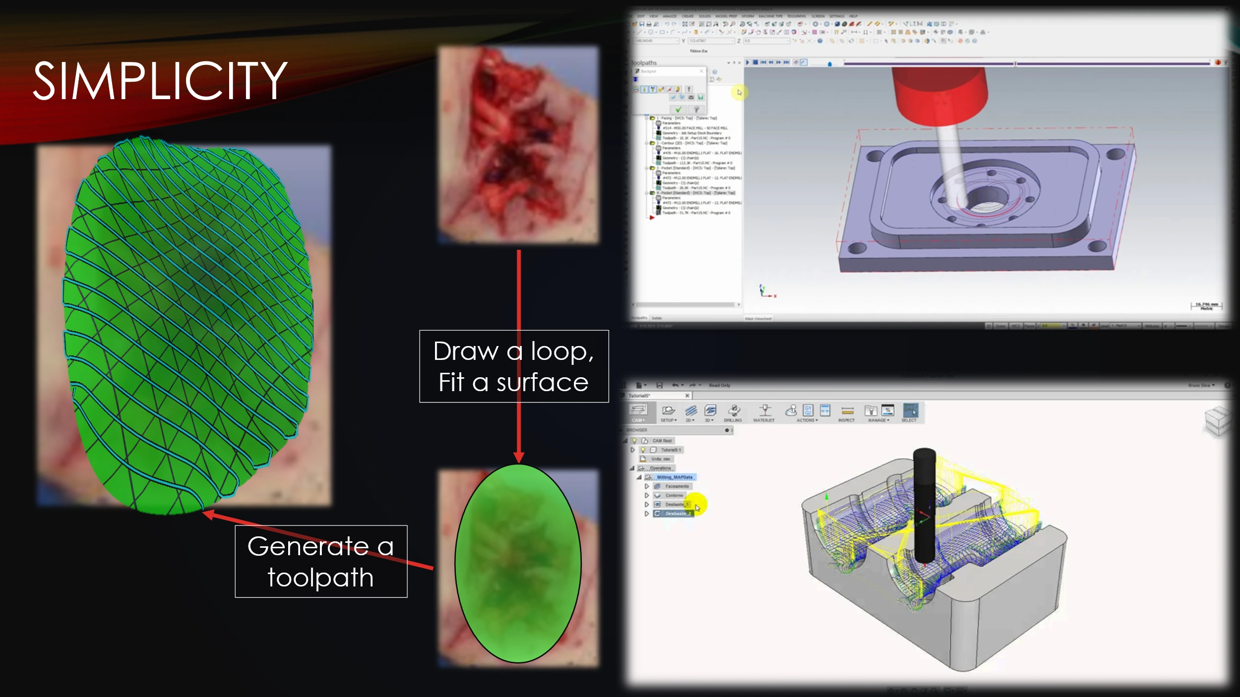 The developed software demonstrates an intuitive workflow, as a surgeon only needs to perform a few simple tasks in order to design a toolpath.
This is in contrast with many other toolpathing programs, where simplicity is sacrificed for indiscriminate precision.
The developed software demonstrates an intuitive workflow, as a surgeon only needs to perform a few simple tasks in order to design a toolpath.
This is in contrast with many other toolpathing programs, where simplicity is sacrificed for indiscriminate precision.
 In terms of accuracy, the software maintains a target toolpath separation more closely than its counterparts do.
The distances between adjacent paths were recorded at each point on a rectilinear toolpath pattern, shown here.
The data was then visualized with a histogram and kernel density plot.
Very little of the data reaches a percent error above 1.25%, verifying the software’s accuracy.
In terms of accuracy, the software maintains a target toolpath separation more closely than its counterparts do.
The distances between adjacent paths were recorded at each point on a rectilinear toolpath pattern, shown here.
The data was then visualized with a histogram and kernel density plot.
Very little of the data reaches a percent error above 1.25%, verifying the software’s accuracy.
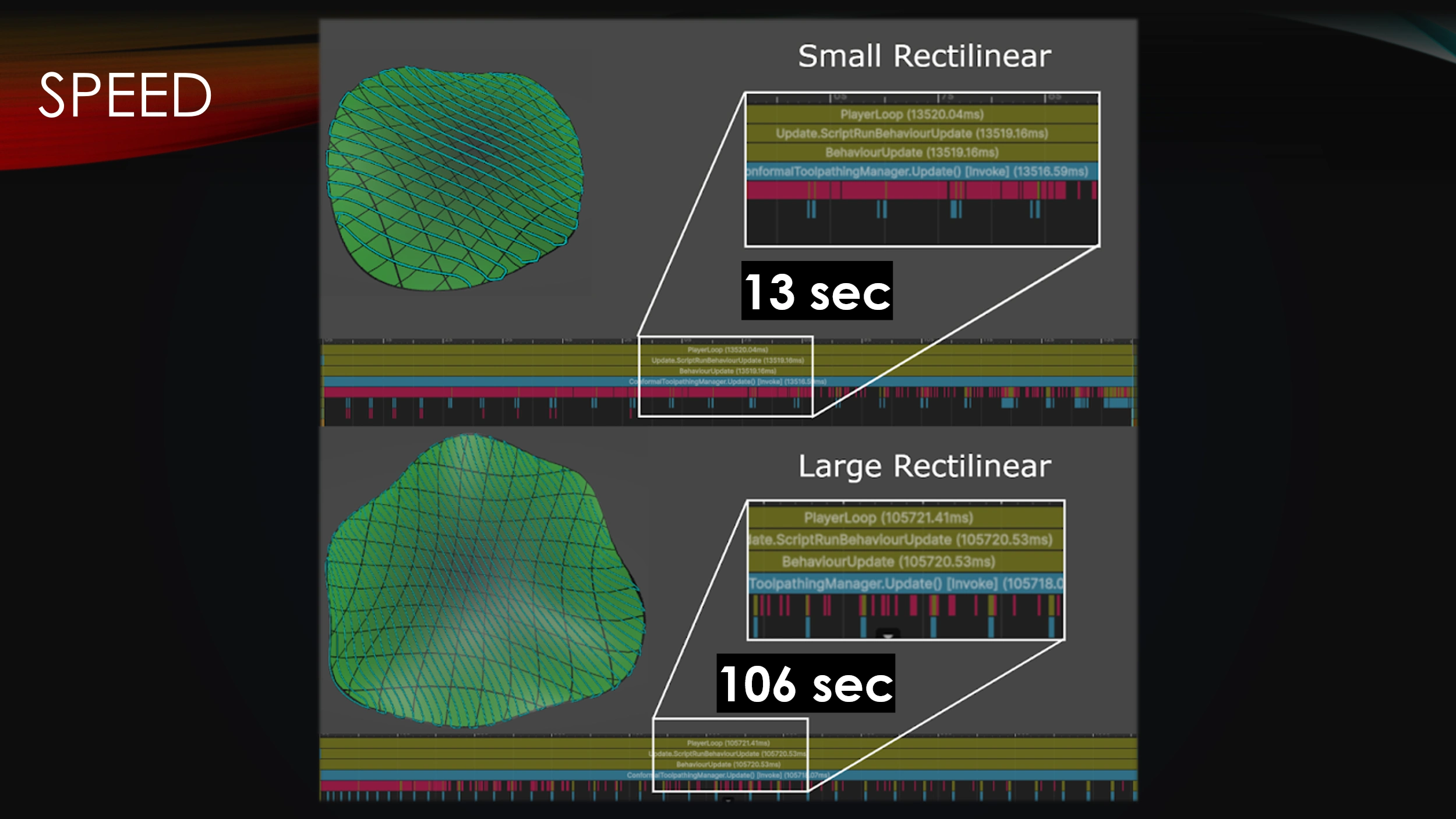 While the simplified workflow attributes greatly to overall software speed, it must also be able to computationally generate the designs in a timely manner.
The main drawback with procedural toolpath generation is that it is slow.
Runtimes were recorded for generation of a small surface as well as a larger surface.
Even though the surface size only doubled, the computation time grew by about ten times.
The procedural algorithm, by itself, will not scale nicely as more and more toolpath resolution is needed.
While the simplified workflow attributes greatly to overall software speed, it must also be able to computationally generate the designs in a timely manner.
The main drawback with procedural toolpath generation is that it is slow.
Runtimes were recorded for generation of a small surface as well as a larger surface.
Even though the surface size only doubled, the computation time grew by about ten times.
The procedural algorithm, by itself, will not scale nicely as more and more toolpath resolution is needed.
 Fortunately, there are ways to improve the procedural algorithm.
Chunking & compute shaders are two optimization methods that can be used to reduce compute time.
Currently, the algorithm iterates over all vertices of the toolpath for every step, but the surface could instead be split into chunks, meaning that only a fraction of the path is run.
Similarly, we can use compute shaders which are programs that are run on the GPU instead of the CPU.
This enables multiple algorithms to be run simultaneously, reducing compute time.
Fortunately, there are ways to improve the procedural algorithm.
Chunking & compute shaders are two optimization methods that can be used to reduce compute time.
Currently, the algorithm iterates over all vertices of the toolpath for every step, but the surface could instead be split into chunks, meaning that only a fraction of the path is run.
Similarly, we can use compute shaders which are programs that are run on the GPU instead of the CPU.
This enables multiple algorithms to be run simultaneously, reducing compute time.
All-in-all, the software rigorously achieves simplicity and accuracy, with solvable issues in program speed.
 Thank you.