Student Steel Bridge Competition
The Student Steel Bridge Competition, organized by the American Institute of Steel Construction, is an annual event where schools compete to design, fabricate, and construct the strongest bridge in the nation. Additionally, there are also 20 regional competitions that decide who qualifies to compete in the nationals. A total of 195 schools competed in regional competitions in 2025, with 43 schools moving onto nationals.
I was chosen as CalPolyPomona's design captain for the 2024-2025 school year.
(note: to view image caption information, hover on desktop or long-press on mobile)
LMB: Rotate RMB: Pan Scroll: Zoom
Background
Basic SSBC rules require that teams design a 20ft steel bridge that can withstand a total load of 2500lbs.
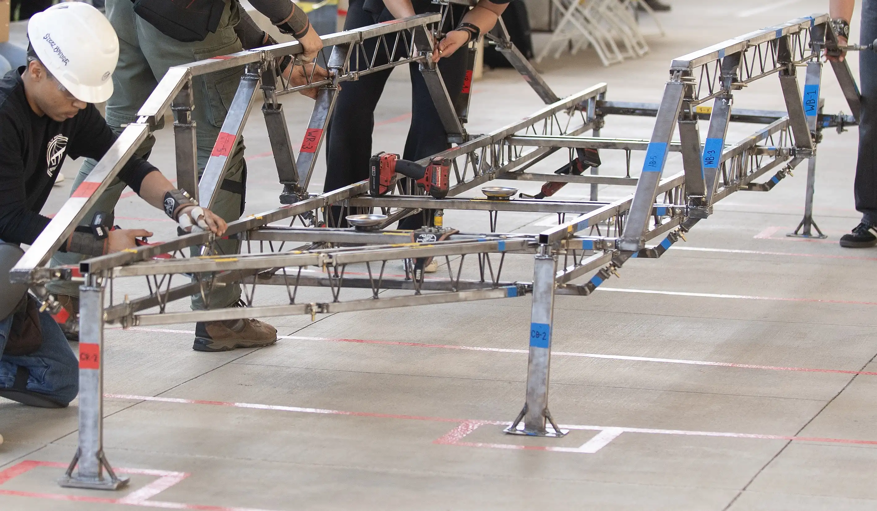
Additionally, the bridge must be assembled on-site from individual 3.5ft pieces (members) during timed construction.
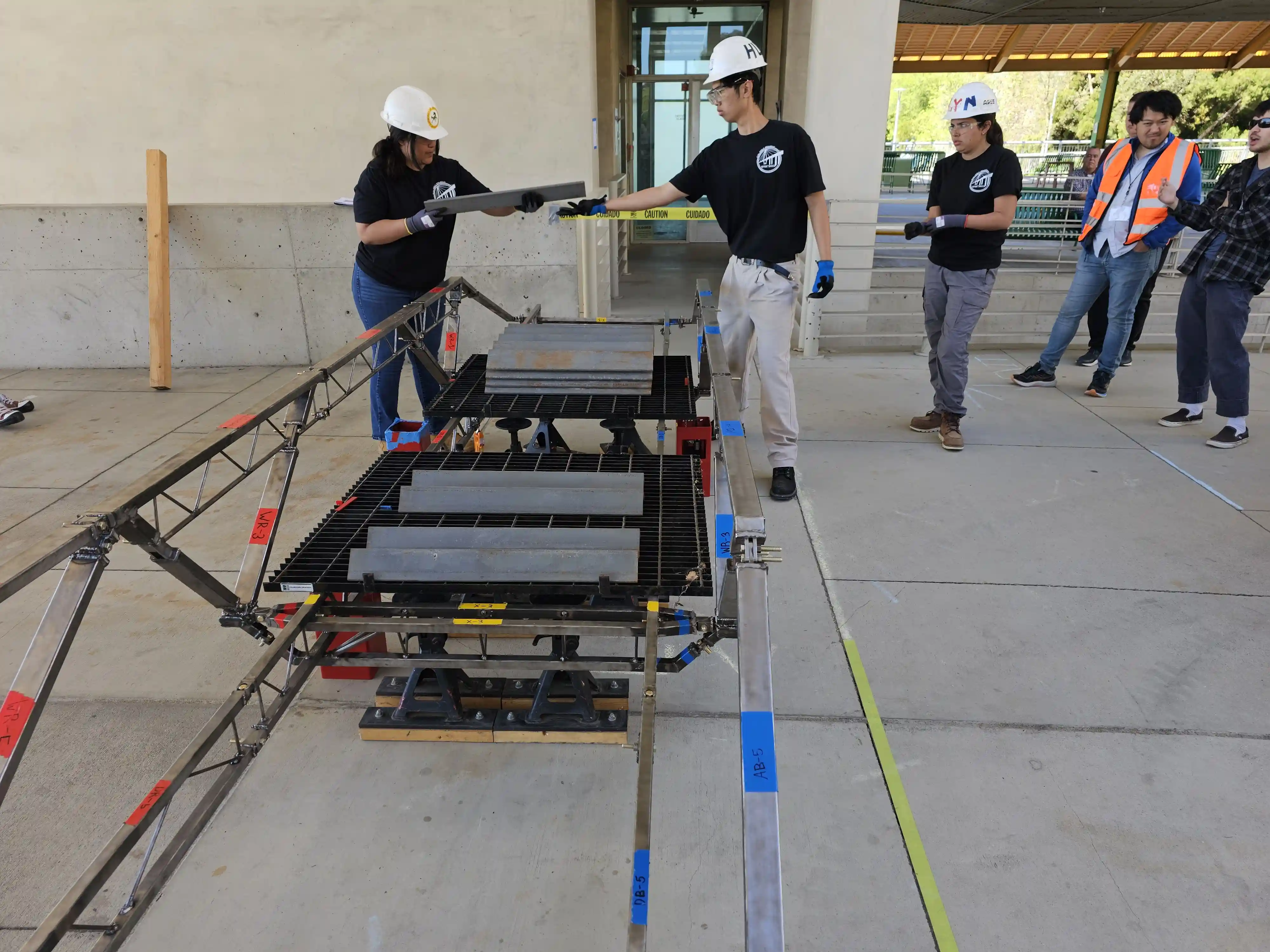
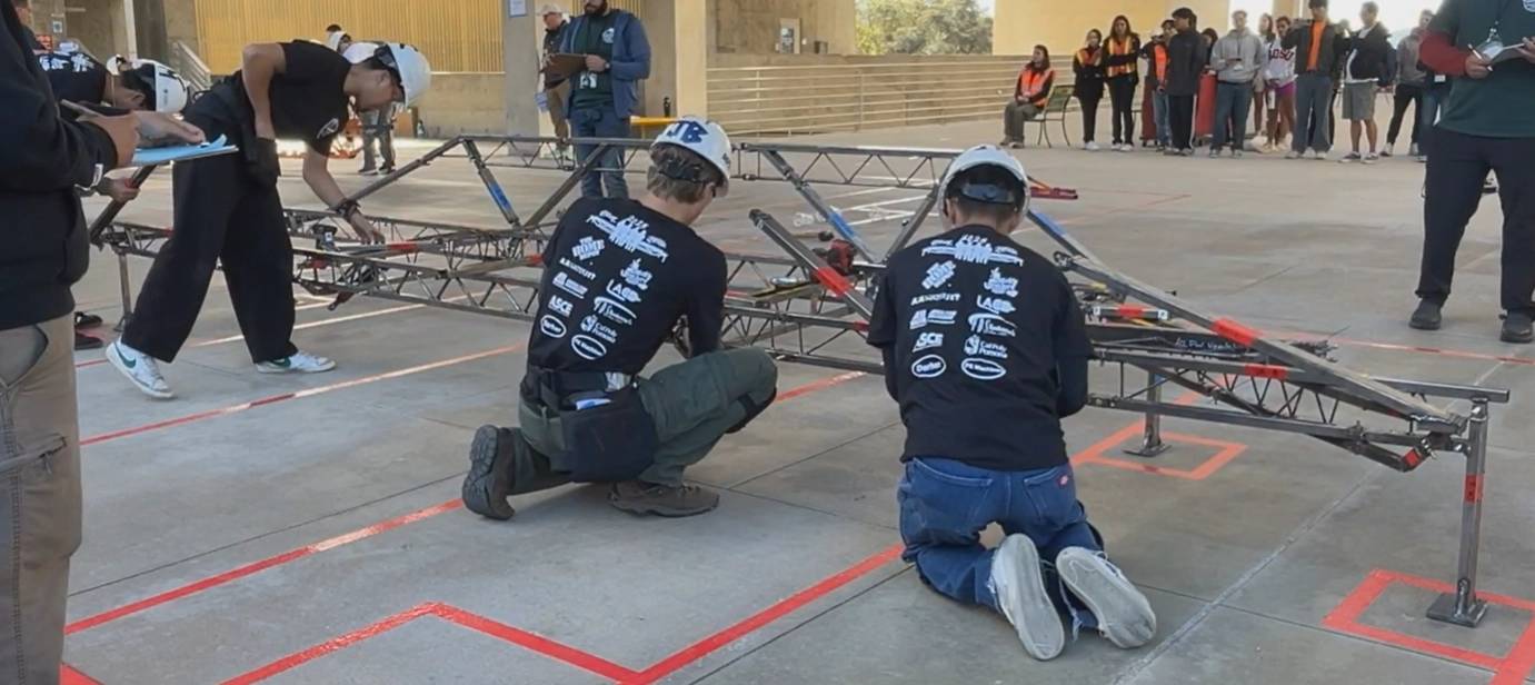
A team's overall score is determined by their bridge's structural efficiency and build-team's construction economy.
Structural Efficiency
The total weight of the bridge is recorded after timed construction.
The amount that the bridge deflects under the 2500lbs load is also recorded.
Common challenges when trying to achieve structural efficiency include:
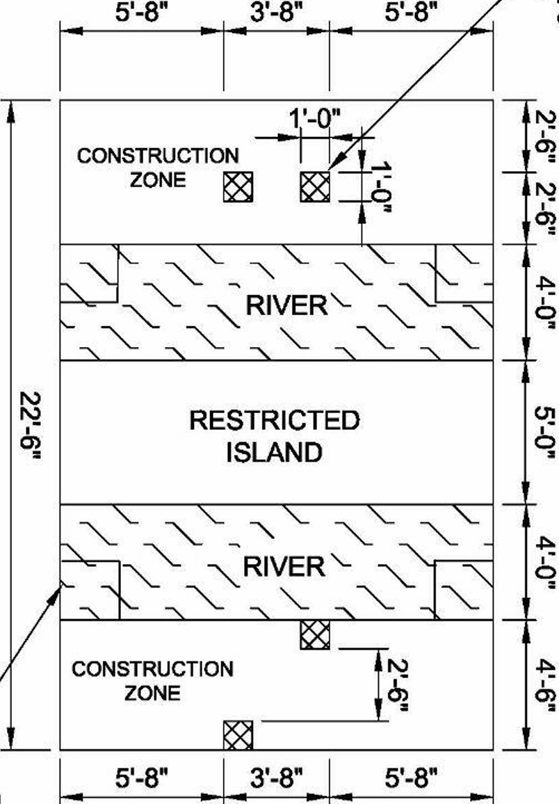
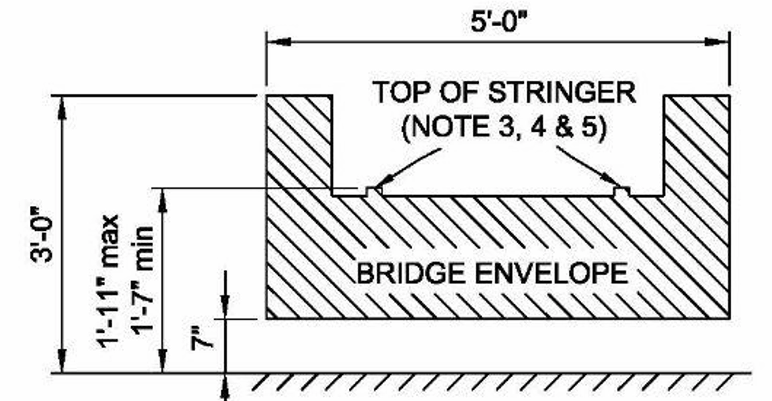
- Designing truss geometry that fits inside the provided boundaries (figure below).
- Finding the balance between light/flexible steel, and heavy/rigid steel.
- Accommodating for constructibility, as an efficient structure is not necessarily a constructable one.

Construction Economy
While the objective is to create a light and stiff bridge, not taking constructibility into account will lower a team's total score considerably.
Construction economy is a function of time taken & builders used.
The building area is divided into five sections: 2 construction zones, 2 rivers, and restricted island.
What's important to note is that a builder in the construction zone counts as 1 builder, but a builder in the river, AKA a barge, counts as 2.1 builders. No builder can be placed in the restricted island.
The effective size of the gap between the two halves of the building area is very important to consider.
Gaps can range between 5ft, 9ft, and 13ft, depending on if a team chooses to use 2, 1, or 0 barges.
The objective is to design a bridge that is light, stiff, and can be built quickly without the need for barges.
Initial Design
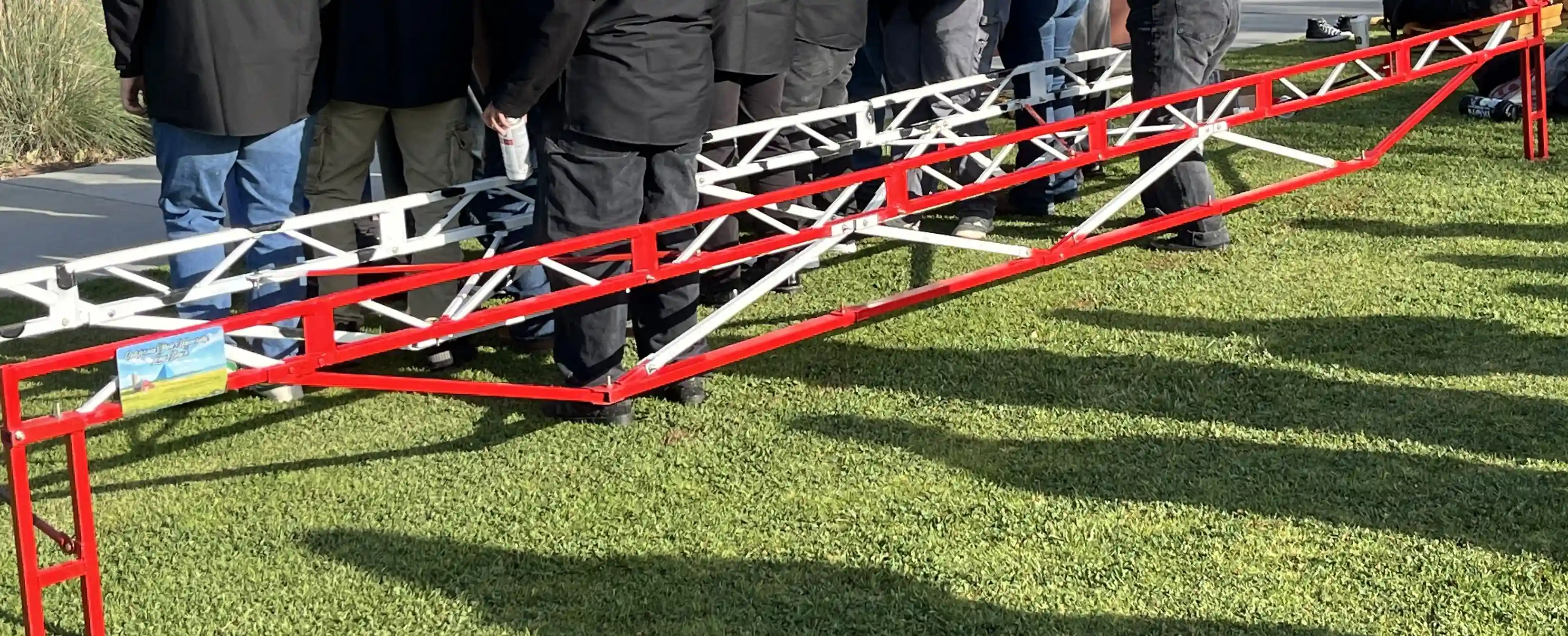
This year, the team chose an arch design as opposed to a traditional under-decking design.
A benefit to this approach is that the envelope allowed for a structure with a greater vertical depth when using an arch compared to using an under-decking.
Additionally, the arch design promised safer construction, as members close to the ground run the risk of construction penalties, such as dropping members or PPE.
On the other hand, the arch design was not without its challenges.
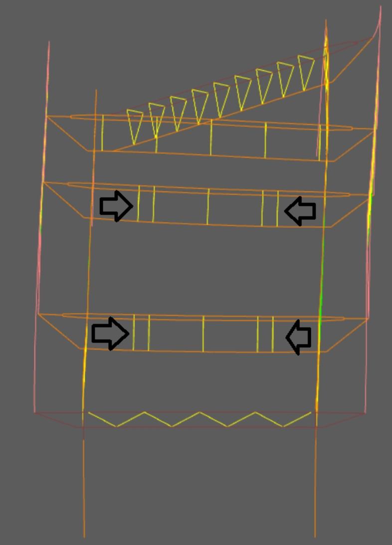
Since the load is placed eccentrically from the supporting structure, the use of sturdy transverse beams was required, which increases overall weight.
The arch design also requires more members and more connections than a lower decking bridge, increasing the complexity of the overall design and affecting construction speed.
Design Inspiration
Last year, University of Florida (UFL) competed and placed first nationally.
Something to note about their bridge is that there is no trussing at the mid-span.
Despite this lack of trussing, the bridge supported the applied load with the smallest deflection of all the competitors.
After our team analyzed the bridge, we concluded that, since trussing is used to resist shearing forces, and there is less shear at the mid-span, the trussing could be removed from the middle, reducing weight while retaining structural integrity.

The advantage of UFL’s design was that barges weren’t necessary for construction.
Due to very little of the structure existing at the mid-span, there was not a need for builders close to the middle.
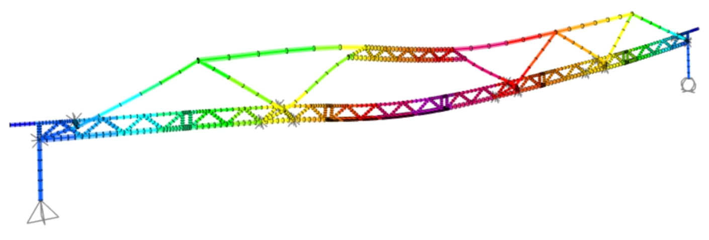
This idea helped inspire the initial arch design, a bridge with a truss-less gap in the mid-span.
Considerations
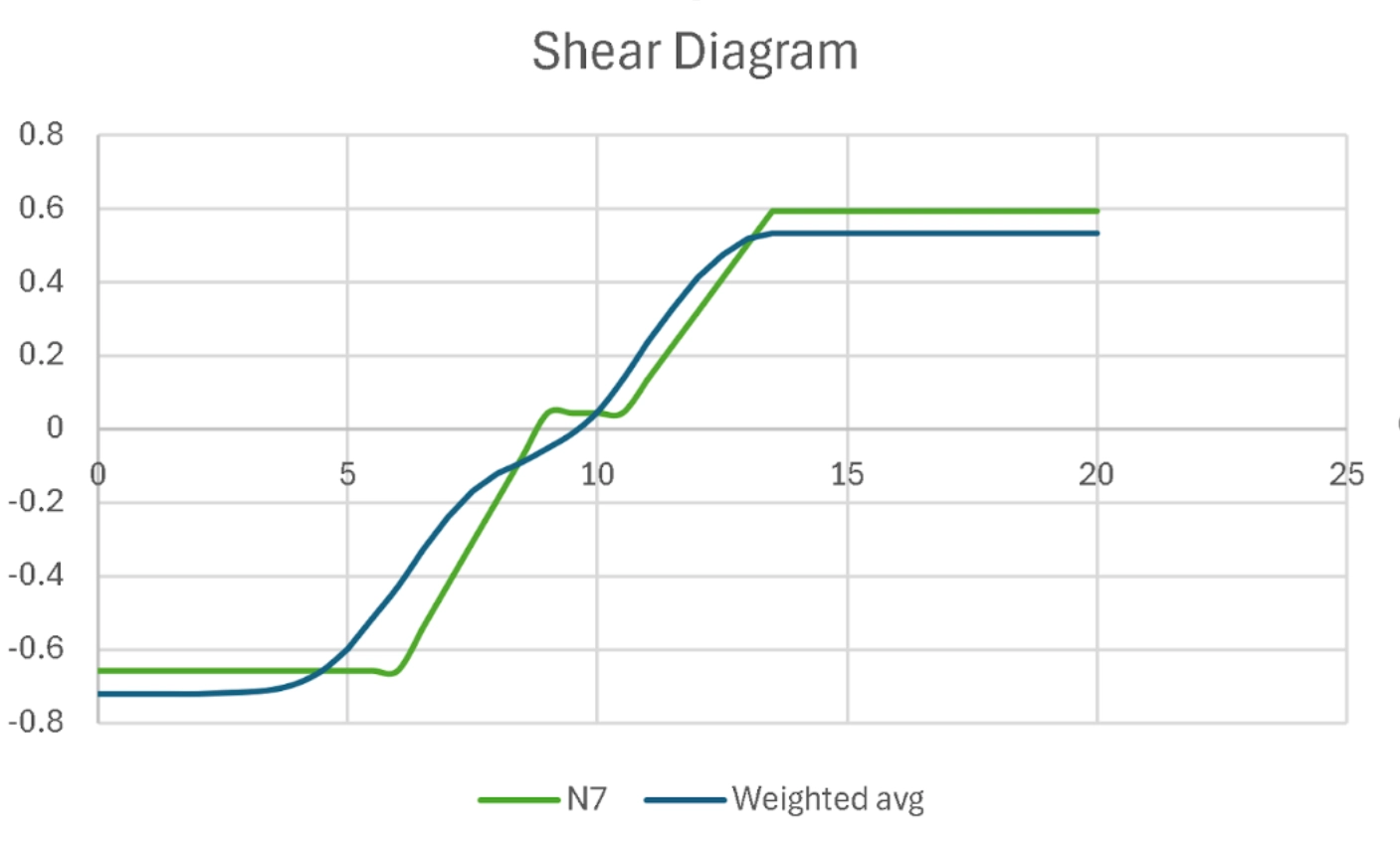
A shear diagram of the competition load was used to visualize shear forces across the bridge, to better determine the best location for the gap, which was between the 8ft and 12ft locations.
Additional research was also conducted to improve the initial design of the bridge.
Structural Innovation: Combining Classic Theories With New Technologies
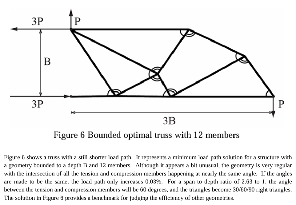
, by William F. Baker, is a paper about an iterative approach to geometry optimization in trusses.
I used the findings about similar angles on pages 5&6 to assist in overall design.

Intermediate to Final Design
After the initial linework was created, steel tube dimensions (sections) needed to be chosen, and safety analysis needed to be conducted.
Sectioning
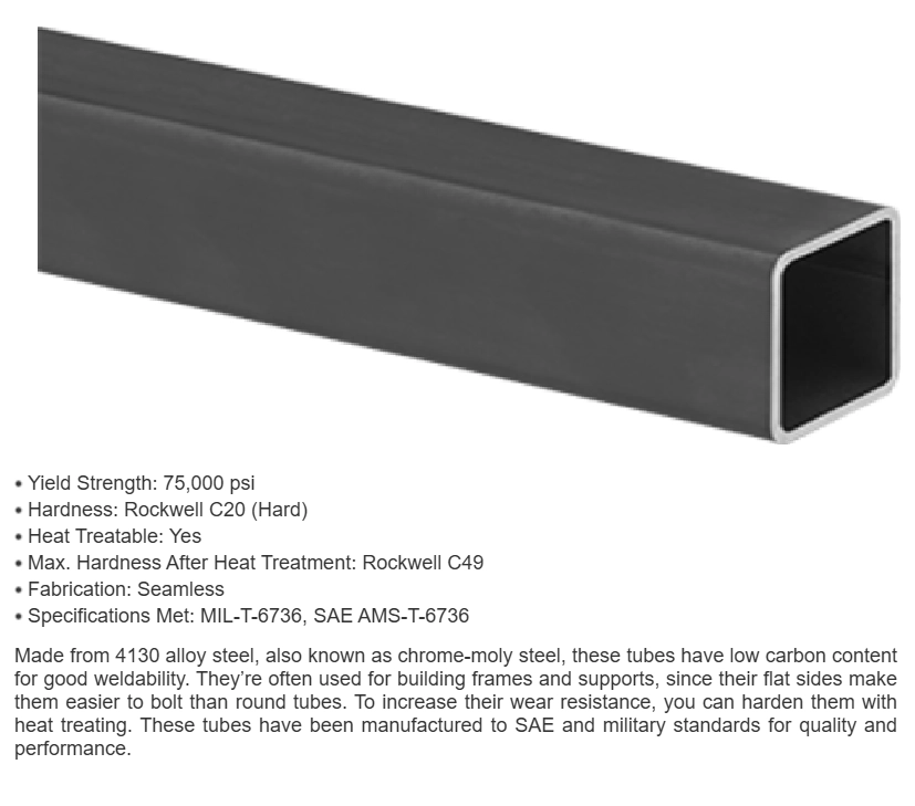
I specified the cross-sectional dimensions of each trussing element. Each section was chosen to minimize elastic deformation under load while also maintaining a low bridge weight.
This was done with a guess-and-check method of iteration, although the process was simplified by logistical limitations on fabrication and construction.
Limitations such as thin sections being impossible to work with and thick sections making members too heavy to carry.
Nonlinear Analysis

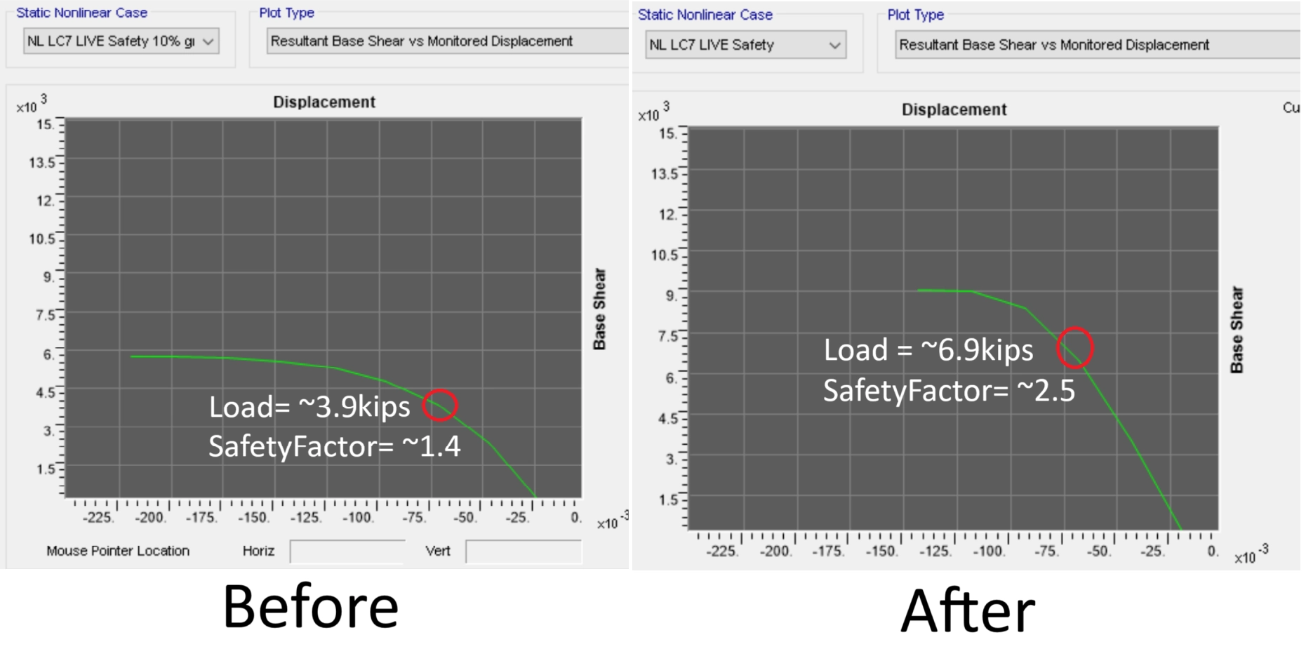
While most of the initial structural analysis was done in SAP2000's linear FEA solver, structural integrity also required nonlinear analysis to be performed.
Linear solvers do not account for how the structure's own deformation can effect stiffness, meaning that they cannot predict complex buckling failures.
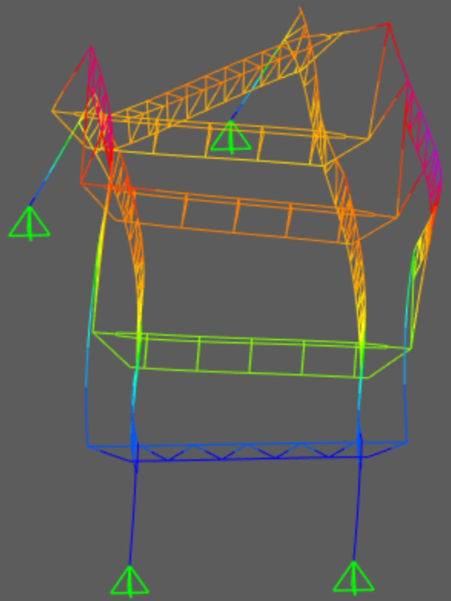
Pushover curves were generated which highlighted the maximum load before failure.
Additionally, nonlinear analysis showed the type of failure at maximum load.
Using this information, I was able to locate the weakest parts of the bridge.
After many iterations of tweaking geometries and cross sections, I was able to verify a safety factor of 2, meaning only a load of >5000lbs would cause the bridge to fail.
